

 Date: Nov.13.2026
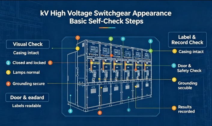
Visual self inspection serves as the first line daily maintenance measure for high voltage switchgear, which can discover early external defects before internal electrical faults occur. This set of basic self check procedures applies to routine patrol, pre commissioning acceptance and periodic offline inspection scenarios, and operators need to implement step by step observation from outside to inside without opening live compartments. The first phase focuses on overall outer contour observation. Inspectors stand at a proper distance to observe the overall posture of the whole cabinet unit, check whether the cabinet body has obvious tilting, deformation or partial bulging caused by long term mechanical stress. Operators need to confirm the alignment between adjacent cabinet units, observe gaps at cabinet joint positions, and mark uneven seam width that exceeds normal tolerance. At the same time, operators check the bottom fixing state, observe whether anchor bolts show loosening, rust or missing accessories, and confirm no foreign stacking debris accumulates around the cabinet foundation that would block heat dissipation channels. This preliminary general scan filters out large scale mechanical abnormalities and provides preparation for detailed partial checking.
The second step targets door assembly, lock structures and sealing components. Every cabinet door needs to be observed for surface warping, and test closing state to judge whether doors can fit tightly with cabinet frame. Check all locking handles, mechanical interlock devices and door latches for deformation, surface corrosion or jammed movement. Sealing rubber strips distributed along door frames are key observation objects: inspectors look for aging hardening, partial cracking, falling off and permanent compression deformation. Damaged sealing strips will allow dust, moisture and humid air to enter inner cabinet chambers, accelerating insulation component aging and raising hidden danger of flash over under high voltage operating conditions. Operators also check observation windows, confirm transparent panels have no crack, scratch or internal fogging phenomenon, and ensure window fastening parts remain intact without looseness.
The third step expands to marking, wiring channel and external auxiliary component appearance. Verify that safety warning labels, rated parameter nameplates and operation indication marks are complete, flat and legible, without heavy fading, peeling or contamination covering key information. Observe external cable inlet and outlet positions, check cable sealing glands for cracking, and confirm no obvious water trace accumulation around cable penetrating holes. External auxiliary parts including exhaust valves, pressure relief covers and grounding connection terminals should be checked for physical integrity. In the final self check link, operators sort out all discovered appearance defects, classify them into minor cosmetic defects and safety related mechanical defects. Safety level abnormal points cannot be ignored just because internal electric functions still work normally. All recorded appearance problems shall be filed, and corresponding maintenance or replacement work shall be arranged according to on site power off conditions to maintain reliable long term operation of high voltage switchgear.

 Prev


 Oct.29.2026