

 Date: Nov.09.2026
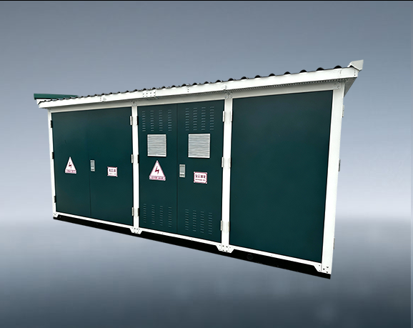
European style box substation belongs to widely applied prefabricated power distribution equipment in urban and rural power networks. Its overall structure adopts compartment divided layout, and independent cabins separate high voltage switching units, power transformers and low voltage distribution units. Clear physical isolation among each functional cabin improves operation safety and facilitates targeted inspection and component replacement. The whole equipment completes assembly, wiring and partial performance debugging in manufacturing workshops. After transportation to project sites, only foundation fixing, cable access and overall commissioning work are needed to realize power supply input. Such structural characteristics make european style substations fit urban community power supply, road side power distribution, industrial park supporting power facilities and many other application occasions.
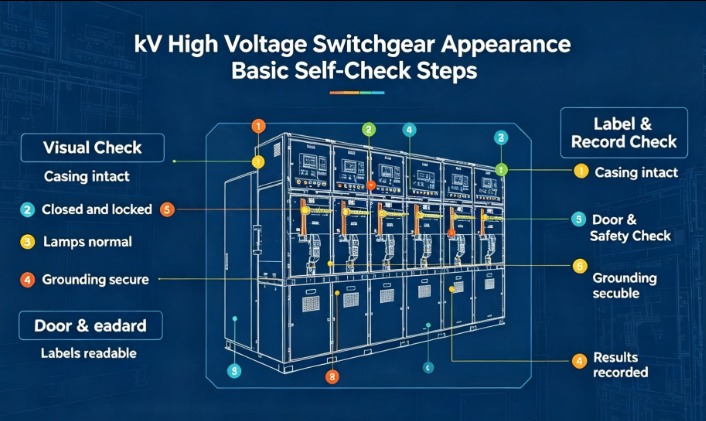
The high voltage cabin forms the power input section of european style substation. This cabin accommodates high voltage switchgear, incoming and outgoing cable interfaces, high voltage protection and measuring components. It undertakes tasks of receiving medium voltage power supply from upper level power grid, completing circuit switching and fault protection. Cabin shell has certain anti impact and weather resistant capability. Inter locking mechanical structures are configured to enforce safe operation sequences, preventing operators from entering live compartments under mis operation conditions. Ventilation and temperature monitoring devices inside the cabin keep working temperature within normal range for high voltage elements. All operation windows and maintenance access doors are set according to operation ergonomics, which supports routine switching operation and equipment overhaul work.
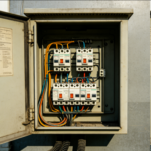
Transformer cabin and low voltage cabin constitute energy conversion and power output parts for european style substation. The transformer cabin places the power transformer that completes medium voltage to low voltage energy conversion. Corresponding heat dissipation channels are designed for transformer heating demands. Some structural versions adopt forced air cooling to enhance heat dissipation under heavy load conditions. Isolation barriers separate transformer units from adjacent cabins to block heat transfer and fire spread risk. The low voltage cabin gathers low voltage incoming switches, outgoing feeders, metering modules and auxiliary protection devices. Electric energy converted by the transformer enters low voltage cabin, then distributes to each end user circuit through multiple outgoing loops. The three cabin independent layout defines clear functional boundaries, helps fault location, and reduces fault spreading scope inside european style substation equipment.

 Prev


 Oct.23.2026